
John Deere 120 Excavator Technical Manual - Operation & Test (TM1659)
Complete Technical Diagnostics, Operation and Test Manual with Electrical Wiring Diagrams for John Deere 120 Excavators, with all the workshop information to maintain, diagnose, and service like professional mechanics.
John Deere Excavator 120 workshop Diagnosis & test manual includes:
* Numbered table of contents easy to use so that you can find the information you need fast.
* Detailed sub-steps expand on repair procedure information
* Numbered instructions guide you through every repair procedure step by step.
* Troubleshooting and electrical service procedures are combined with detailed wiring diagrams for ease of use.
* Notes, cautions and warnings throughout each chapter pinpoint critical information.
* Bold figure number help you quickly match illustrations with instructions.
* Detailed illustrations, drawings and photos guide you through every procedure.
* Enlarged inset helps you identify and examine parts in detail.
TM1659 - John Deere 120 Excavator Operation & Test Service Manual.PDF
TM1659 - John Deere 120 Excavator Operation & Test Service Manual.epub
Total Pages: 836 pages
File Format: PDF/EPUB/MOBI/AZW (PC/Mac/Android/Kindle/iPhone/iPad; bookmarked, ToC, Searchable, Printable)
Language: English
MAIN SECTIONS
Foreword
Technical Information Feedback Form
General Information
Safety
Diagnostics
Main Controller (MCZ) Diagnostic Trouble Codes
Engine Control Unit (ECU) Diagnostic Trouble Codes
Monitor Controller (DSZ) Diagnostic Trouble Codes
Air Conditioner Controller (ACF) Diagnostic Trouble Codes
Operational Checkout Procedure
Operational Checkout Procedure
Engine
Theory of Operation
Diagnostic Information
Adjustments
Tests
Electrical System
System Information
System Diagrams
Sub-System Diagnostics
Monitor Operation
References
Power Train
Theory of Operation
Diagnostic Information
Hydraulic System
Theory of Operation
Diagnostic Information
Tests
Heating and Air Conditioning
Theory of Operation
Diagnostic Information
Tests
Dealer Fabricated Tools
tm1659 - 120 Excavator Operation and Tests
Table of Contents
Foreword
Technical Information Feedback Form
Section 9000: General Information
Group 01: Safety
Follow Safe Procedures
Prepare for Emergencies
Prevent Acid Burns
Handle Chemical Products Safely
Handle Fluids Safely-Avoid Fires
Avoid High-Pressure Fluids
Warn Others of Service Work
Support Machine Properly
Operate Only from Operator's Seat
Park Machine Safely
Stay Clear of Moving Parts
Avoid Power Lines
Use Handholds and Steps
Keep Riders Off Machine
Move and Operate Machine Safely
Wear Protective Clothing
Protect Against Flying Debris
Protect Against Noise
Illuminate Work Area Safely
Service Machines Safely
Remove Paint Before Welding or Heating
Avoid Heating Near Pressurized Fluid Lines
Beware of Exhaust Fumes
Use Proper Lifting Equipment
Service Cooling System Safely
Dispose of Waste Properly
Work in a Clean Area
Use Tools Properly
Replace Safety Signs
Live With Safety
Group 02: General Specifications
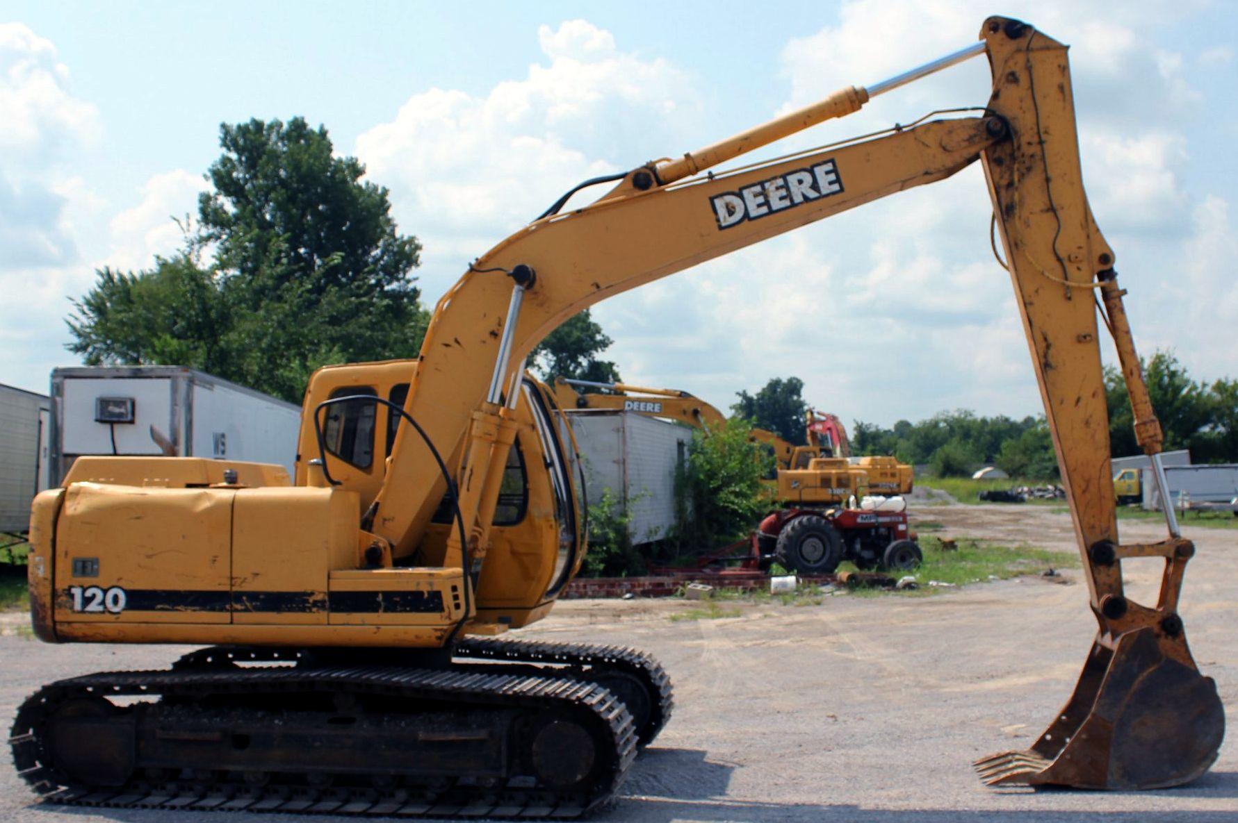
120 Excavator Overview
120 Excavator
120 Working Ranges
Engine Specifications
Drain and Refill Capacities
Lift Capacity-KG (LB)
Lift Capacity-KG (LB)
Lift Capacity-KG (LB)
Lift Capacity-KG (LB)
Lift Capacity-KG (LB)
Lift Capacity-KG (LB)
Group 03: Torque Values
Hardware Torque Specifications
Unified Inch Bolt and Cap Screw Torque Values
Metric Bolt and Cap Screw Torque Values
Additional Metric Cap Screw Torque Values
Check Oil Lines And Fittings
Service Recommendations for O-Ring Boss Fittings
Service Recommendations For Flat Face O-Ring Seal Fittings
Service Recommendations for 37° Flare and 30° Cone Seat Connectors
Service Recommendations For Flared Connections-Straight or Tapered Threads
Service Recommendations For Inch Series Four Bolt Flange Fittings
Service Recommendations for Metric Series Four Bolt Flange Fitting
Group 04: Fuels and Lubricants
Diesel Fuel
Lubricity of Diesel Fuels
Low Sulfur Diesel Fuel Conditioner
Diesel Fuel Storage
Fuel Tank
Do Not Use Galvanized Containers
Diesel Engine Oil
Hydraulic Oil
Swing Gearbox, Propel Gearbox and Pump Gearbox Oils
Track Roller, Front Idler, and Carrier Roller Oil
Track Adjuster, Working Tool Pivot, Swing Bearing, and Swing Bearing Gear Grease
Oil Filters
Alternative and Synthetic Lubricants
Mixing of Lubricants
Section 9005: Operational Checkout Procedure
Group 10: Operational Checkout Procedure
Operational Checkout
Section 9010: Engine
Group 05: Theory of Operation
POWERTECHPOWERTECH is a trademark of Deere & Company. 4.5 L (4045) John Deere Engine-Use CTM104
Engine-Sectional View
Fan Drive Operation
Engine Speed Control System Operation
Engine RPM Dial Speed Control Circuit Operation
E (Economy) Mode Speed Control Circuit Operation
HP (High Power) Mode Speed Control Circuit Operation
Auto-Idle Mode Speed Control Circuit Operation
Engine Speed Learning Control Circuit Operation
Group 15: Diagnostic Information
POWERTECHPOWERTECH is a trademark of Deere & Company. 4.5 L (4045) John Deere Engine-Use CTM104
Diagnose Engine Malfunctions
Group 20: Adjustments
POWERTECHPOWERTECH is a trademark of Deere & Company. 4.5 L (4045) John Deere Engine-Use CTM104
JT05801 Clamp-On Electronic Tachometer Installation
Check and Adjust Fuel Shut-Off Solenoid Linkage
Engine Speed Check
Injection Pump Fast and Slow Idle Stops Adjustment
Engine Control Motor and Sensor Adjustment
Engine Speed Learning Procedure
Cooling System Fill and Deaeration
Group 25: Tests
POWERTECHPOWERTECH is a trademark of Deere & Company. 4.5 L (4045) John Deere Engine-Use CTM104
JT05801 Clamp-On Electronic Tachometer Installation
Fuel Line Leakage Test
Air Filter Restriction Indicator Switch Test
Air Intake System Leakage Test
Radiator Air Flow Test
Engine Power Test Using Turbocharger Boost Pressure
Section 9015: Electrical System
Group 05: System Information
Electrical System Visual Inspection
Electrical Circuit Malfunctions
High Resistance Circuit
Open Circuit
Grounded Circuit
Shorted Circuit
Sensor Circuit Shorted to Power
Sensor Circuit Shorted to Itself
Sensor Circuit Shorted to Ground
Multimeter
Seven Step Electrical Test Procedure
Schematic, Wiring Diagram, and Component Location Information
Reading a System Functional Schematic
Reading a Wiring Diagram
Reading a Component Location Diagram
Reading a Connector End View Diagram
Electrical Schematic Symbols
Group 10: System Diagrams
Fuse Specifications
Fuse (Blade-Type) Color Codes
Component Identification Table
Functional Schematic and Component Location Legend
System Functional Schematic Section Legend
System Functional Schematic (SE1-SE3)
System Functional Schematic (SE4-SE6)
System Functional Schematic (SE7-SE9)
System Functional Schematic (SE10-SE12)
System Functional Schematic (SE13-SE15)
System Functional Schematic (SE16-SE17)
Engine and Frame Harness (W1) Component Location
Engine and Frame Harness (W1) Connectors, Wire and Pin Location
Cab Harness (W2) Component Location
Cab Harness (W2) Component Location-Detail A (Harness Mating Connectors)
Cab Harness (W2) Component Location-Detail B (Fuse Block)
Cab Harness (W2) Connectors, Wire and Pin Location
Monitor and Relay Harness (W3) Component Location
Monitor and Relay Harness (W3) Component Location-Detail A (Monitor Controller Connectors)
Monitor and Relay Harness (W3) Component Location-Detail B (Monitor Controller Indicators)
Monitor and Relay Harness (W3) Connectors, Wire and Pin Location
Group 15: Sub-System Diagnostics
Power Circuit Operational Information
Power Circuit Theory of Operation
Power Circuit Schematic
Charging Circuit Operational Information
Charging Circuit Theory Of Operation
Charging Circuit Schematic
Alternator Theory of Operation
Starting and Fuel Shutoff Circuit Operational Information
Starting and Fuel Shutoff Circuit Theory of Operation
Starting and Fuel Shutoff Circuit Schematic
Windshield Wiper and Washer Circuit Operational Information
Windshield Wiper and Washer Circuit Theory of Operation
Windshield Wiper and Washer Circuit Schematic
Work and Drive Light Circuit Operational Information
Work and Drive Light Circuit Theory of Operation
Work and Drive Light Circuit Schematic
Accessory Circuits Operational Information
Accessory Circuits Theory of Operation
Accessory Circuits Schematic
Heater Circuit Operational Information
Heater Circuit Theory of Operation
Heater Circuit Functional Schematic
Monitor Controller and Display Circuit Specifications
Monitor Controller and Display Circuit Operational Information
Monitor Controller and Display Circuit Theory of Operation
Monitor Controller and Display Circuit Schematic
Engine and Pump Controller Circuit Operational Information
Engine and Pump Controller Circuit Theory of Operation
Engine and Pump Controller Circuit Schematic
Travel Alarm Circuit Operational Information
Travel Alarm Circuit Theory of Operation
Travel Alarm Circuit Schematic
Group 20: References
Battery Operation
Battery Specifications
Diagnose Battery Malfunctions
Check Battery Electrolyte Level and Terminals
Procedure for Testing Batteries
Using Booster Batteries-24 Volt System
Replacing Batteries
Adding 12 or 24 Volt Accessories
Changing Travel Alarm Volume
Proportional Solenoid Test Harness
Pump Control Test Harness
Pump Pressure Sensor Test Harness
Section 9020: Power Train
Group 05: Theory of Operation
Track Adjuster and Recoil Spring Operation
Propel Gearbox Operation
Group 15: Diagnostic Information
Diagnose Undercarriage Components Malfunctions
Measure Track Chain Bushing Wear
Measure Track Chain Link Wear
Measure Track Chain Pitch
Measure Track Shoe Grouser Wear
Measure Track Roller Wear
Measure Track Carrier Roller Wear
Measure Front Idler Wear
Measure Swing Bearing Wear
Group 20: Adjustments
Adjust Track Sag
Adjust Track Sag-Rubber Track
Section 9025: Hydraulic System
Group 05: Theory of Operation
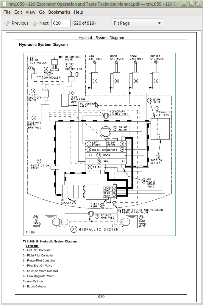
Hydraulic System Diagram
Pilot Pump Operation
Pilot Pressure Regulating Valve and Filter Operation
Pilot Shut-Off Valve Operation
Pilot Controller Operation-Neutral
Pilot Controller Operation-Metering and Full Stroke
Propel Pilot Controller Operation
Pilot Controller Operation of Control Valve
Flow Regulator Valve Operation
Hydraulic Pump and Drive Gearbox Operation
Hydraulic Pump Operation
Hydraulic Pump Regulator Components Operation
Hydraulic Pump Regulator Operation
Hydraulic Pump Regulator Increasing, Maximum, and Decreasing Operation
Hydraulic Pump Regulator Summation Operation
Proportional Solenoid Valve Manifold Operation
Proportional Solenoid Valve Operation
Control Valve Operation
Control Valve Circuit Schematic
Control Valve Pilot Pressure Signal Passages Operation
Control Valve Neutral and Power Passages Operation
System Relief Valve Operation
Circuit Relief and Anti-Cavitation Valve Operation
Pump Control Valve Operation
Flow Combiner Valve Operation
Arm Regenerative Valve Operation
Boom and Arm Reduced Leakage Valves Operation
Bucket Flow Control Valve Operation
Propel Flow Control Valve Operation
Propel-Boom Down Selector Valve Operation
Boom Regenerative Valve Operation
Propel and Arm In Combined Operation
Swing and Boom Up Combined Operation
Swing Gearbox Operation
Swing Motor and Park Brake Operation
Swing Motor Crossover Relief and Cushion Valve Operation
Swing Motor Park Brake Release Valve Operation
Rotary Manifold Operation
Propel Motor Operation
Propel Motor Speed Change Operation
Propel Motor Speed Change Circuit Operation
Propel Motor Brake Valve Operation-Neutral
Propel Motor Brake Valve Operation-Propel
Propel Motor Counterbalance Valve Operation-Braking
Hydraulic Cylinder Operation
Return Filter Operation
Hydraulic System Circuit Symbols
Pilot Circuit for Controllers Schematic
Hydraulic Pump and Control Valve Schematic
Hydraulic Pump and Regulator Schematic
Swing Motor Schematic
Propel Motor Schematic
Group 15: Diagnostic Information
Diagnostic Procedure
Diagnose Electronic and Control Valve Component Malfunctions
Diagnose Hydraulic System Malfunctions
Diagnose Pilot Circuit Malfunctions
Diagnose Dig Circuit Malfunctions
Diagnose Swing Circuit Malfunctions
Diagnose Propel System Malfunctions
Control Lever Pattern Conversion
Control Valve Line Identification-Left Front
Control Valve Line Identification-Right Rear
Control Valve Line Identification-Bottom
Control Valve Component Identification-Left Front
Control Valve Component Identification-Right Rear
Control Valve Component Identification-Bottom
Main Hydraulic System Component Location
Pilot Controllers-to-Flow Regulator Component Location-SAE Pattern
Pilot Controllers-to-Flow Regulator Component Location-John Deere Pattern
Pilot Flow Regulator-to-Control Valve Component Location
Propel System Component Location
Pressure and Return System Component Location
Group 20: Adjustment
Pilot Shut-Off Valve Linkage Adjustment
Group 25: Tests
Laptop Computer General Description
Excavator Diagnostics Program-Overview
Excavator Diagnostics Program-Install
Excavator Diagnostics Program-Uninstall
Excavator Diagnostics Program-Starting
Excavator Diagnostics Program Feature-Service Codes
Excavator Diagnostics Program Feature-Monitor Data
Excavator Diagnostics Program Feature-Saving Monitor Data
Excavator Diagnostics Program Special Function-Engine Speed Adjustment
Excavator Diagnostics Program-Service Codes List
Excavator Diagnostics Program-Monitor Data Items
Excavator Diagnostics Program Special Function-Engine Speed Factory Settings Parameters
Engine Speed to Pump Flow Rate Chart
Excavator Diagnostics Program Troubleshooting
Reading Service Codes Without Excavator Diagnostics Program
Engine and Pump Controller Function
JT05801 Clamp-On Electronic Tachometer Installation
JT05800 Digital Thermometer Installation
JT02156A Digital Pressure and Temperature Analyzer Installation
Hydraulic Pump Start-Up Procedure
Pump Drive Gearbox Start-Up Procedure
Swing Motor Start-Up Procedure
Swing Gearbox Start-Up Procedure
Propel Motor Start-Up Procedure
Propel Gearbox Start-Up Procedure
Hydraulic Oil Filter Inspection Procedure
Hydraulic Oil Cleanup Procedure Using Portable Filter Caddy
Hydraulic System Warm-Up Procedure
Lower Boom with Engine Stopped
Arm Regenerative Solenoid Valve (SC) Harness Test
Propel Speed Change Solenoid Valve (SI) Harness Test
Engine Control Sensor (EC Sensor) Harness Test
Engine Control Motor (EC Motor) Harness Tests
Miscellaneous Component Harness Test
Cycle Time Test
Swing Dynamic Braking (Drift) Test
Pilot Pressure Regulating Valve Test and Adjustment
Control Valve Spool Pilot Actuation Pressure Test
System Relief Valve Test and Adjustment
Circuit Relief Valve Test and Adjustment
Swing Motor Crossover Relief Valve Test and Adjustment
Propel Motor Crossover Relief Valve Test and Adjustment
Proportional Solenoid Valve Test and Adjustment
Pump Control Valve Test
Hydraulic Pump Regulator Adjustments
Hydraulic Pump Regulator Test and Adjustment-Minimum Flow
Hydraulic Pump Regulator Test and Adjustment-Maximum Flow
Hydraulic Pump Regulator Test and Adjustment-Engine Pulldown
Hydraulic Pump Flow Test
Pilot Pump Flow Test
Propel System Tracking Test
Cylinder Drift Test-Boom, Arm, and Bucket
Swing Motor Leakage Test
Propel Motor Leakage Test
John Deere 120 Excavator Technical Manual - Operation & Test (TM1659)
![]()