
John Deere 410G Backhoe Loader Technical Manual (Operation & Test) (TM1881)


Complete Diagnosis, Operation and Test Service Manual with Electrical Wiring Diagrams for John Deere 410G Backhoe, with all the shop information to maintain, test, and service like professional mechanics.
John Deere 410G Backhoe Loader workshop Operation and Test repair manual includes:
* Numbered table of contents easy to use so that you can find the information you need fast.
* Detailed sub-steps expand on repair procedure information
* Numbered instructions guide you through every repair procedure step by step.
* Troubleshooting and electrical service procedures are combined with detailed wiring diagrams for ease of use.
* Notes, cautions and warnings throughout each chapter pinpoint critical information.
* Bold figure number help you quickly match illustrations with instructions.
* Detailed illustrations, drawings and photos guide you through every procedure.
* Enlarged inset helps you identify and examine parts in detail.
TM1881 - John Deere 410G Backhoe Loader Operation and Test Service Manual.PDF
Total Pages: 1,136 pages
File Format: PDF (PC/Mac/Android/Kindle/iPhone/iPad; bookmarked, ToC, Searchable, Printable)
Language: English
TABLE OF CONTENTS
Foreword
Technical Information Feedback Form
General Information
Safety Information
Operational Checkout Procedure
Operational Checkout Procedure
Engine
Theory of Operation
Diagnostic Information
Adjustments
Tests
Electrical System ( - S.N. 951254)
System Information
System Diagrams
Sub-System Diagnostics
Monitor Operation
References
Electrical System (S.N. 951255- )
System Information
System Diagrams
Sub-System Diagnostics
Monitor Operation
References
Power Train
Theory of Operation
System Diagnostic Information
Adjustments
Tests
Hydraulic System
Theory of Operation
Diagnostic Information
Adjustments
Tests
Heating and Air Conditioning
Theory of Operation
Diagnostic Information
Adjustments
Test
exploded view - ToC
9000 - General Information
01 - Safety
Add and Operate Attachments Safely
Avoid Backover Accidents
Avoid High-Pressure Fluids
Avoid Machine Tipover
Avoid Unauthorized Machine Modifications
Avoid Work Site Hazards
Beware of Exhaust Fumes
Dispose of Waste Properly
Drive Metal Pins Safely
Follow Safety Instructions
Handle Chemical Products Safely
Inspect and Maintain ROPS
Inspect Machine
Keep Riders Off Machine
Make Welding Repairs Safely
Operate Only If Qualified
Operating or Traveling On Public Roads
Park and Prepare for Service Safely
Prepare for Emergencies
Prevent Battery Explosions
Prevent Fires
Prevent Unintended Machine Movement342200224For Machines With Pilot Controls
Prevent Unintended Machine Movement
Recognize Safety Information
Remove Paint Before Welding or Heating
Safety Features
Safety Signs
Service Cooling System Safely
Start Only From Operator's Seat
Stay Clear of Moving Parts
Use and Maintain Seat Belt
Use Special Care When Operating
Use Steps and Handholds Correctly
Wear Protective Equipment
9005 - Operational Checkout Procedure
10 - Operational Checkout Procedure
Operational Checkout Procedure
9010 - Engine
05 - Theory of Operation
Engine Sectional View
General Engine Description
POWERTECH 4.5L (4045) and 6.8L (6068) John Deere Engines
15 - Diagnostic Information
Diagnose Engine Malfunctions
Make Visual Inspection of Engine and Supporting Systems
POWERTECH 4.5L (4045) and 6.8L (6068) John Deere Engines_{08}
20 - Adjustments
Engine Speed Control Lever Adjust Tension
Engine Speed Control Linkage Adjustment (S.N. 342200224951254)
Engine Speed Control Linkage (S.N. 951255342200224)
JT05801 Clamp-On Electronic Tachometer Installation
POWERTECH 4.5L (4045) and 6.8L (6068) John Deere Engines_{33}
Slow and Fast Idle (S.N. 342200224951254)
Slow and Fast Idle (S.N. 951255342200224)
25 - Tests
Air Intake System Test Leakage
Fuel Line Test Leakage
Injection Pump Timing (S.N. 342200224951254)
JT05800 Digital Thermometer Installation
JT05801 Clamp-On Electronic Tachometer Installation_{41}
POWERTECH 4.5L (4045) and 6.8L (6068) John Deere Engines_{34}
Radiator Air Flow Test (S.N. 342200224951254)
Turbocharger Boost Pressure342200224Engine Performance Test (S.N. 342200224951254)
Turbocharger Boost Pressure342200224Engine Performance Test (S.N. 951255342200224)
9015A - Electrical System ( 342200224 S.N. 951254)
05 - System Information
Electrical Circuit Malfunctions
Electrical Schematic Symbols
Electrical System Visual Inspection
Grounded Circuit
High Resistance Circuit
Multimeter
Open Circuit
Reading a Component Location Diagram
Reading a Connector End View Diagram
Reading a System Functional Schematic
Reading a Wiring Diagram
Schematic, Wiring Diagram, and Component Location Information
Sensor Circuit Shorted to Ground
Sensor Circuit Shorted to Itself
Sensor Circuit Shorted to Power
Seven Step Electrical Test Procedure
Shorted Circuit
10 - System Diagrams
A _ C Cab Harness (W10) Component Location (S.N. 342200224926435)
A _ C Cab Harness (W10) Component Location (S.N. 926436342200224951254)
A _ C Cab Harness (W10) Wiring Diagram (S.N. 342200224926435)
A _ C Cab Harness (W10) Wiring Diagram (S.N. 926436342200224951254)
A _ C Compressor Harness (W9) Component Location ( 342200224 S.N. 951254)
A _ C Compressor Harness (W9) Wiring Diagram ( 342200224 S.N. 951254)
Attachment Coupler Cowl Harness (W21) Wiring Diagram ( 342200224 S.N. 951254)
Attachment Coupler Harness (W20, W21, and W22) Electrical Component Location ( 342200224 S.N. 951254)
Attachment Coupler Power Harness (W20) Wiring Diagram ( 342200224 S.N. 951254)
Attachment Coupler Solenoid Harness (W22) Wiring Diagram ( 342200224 S.N. 951254)
Cab Roof Harness (W5) Component Location ( 342200224 S.N. 951254)
Cab Roof Harness (W5) Wiring Diagram ( 342200224 S.N. 951254)
Cab _ ROPS Harness (W6) Component Location ( 342200224 S.N. 951254)
Cab _ ROPS Harness (W6) Wiring Diagram ( 342200224 S.N. 951254)
Canopy Heater Control Harness (W15) Component Location ( 342200224 S.N. 951254)
Canopy Heater Control Harness (W15) Wiring Diagram ( 342200224 S.N. 951254)
Component Identification Table ( 342200224 S.N. 951254)
Engine _ Transmission Harness (W7) Component Location ( 342200224 S.N. 951254)
Engine _ Transmission Harness (W7) Wiring Diagram ( 342200224 S.N. 951254)
Fuse and Relay Specifications ( 342200224 S.N. 951254)
Fuse (Blade-Type) Color Codes ( 342200224 S.N. 951254)
Pattern Select Harness (W19) Component Location (S.N. 913484342200224951254)
Pattern Select Harness (W19) Wiring Diagram (S.N. 913484342200224951254)
Pilot Control Harness (W11) Component Location (S.N. 913484342200224951254)
Pilot Control Harness (W11) Wiring Diagram (S.N. 913484342200224951254)
Pilot Control Harness (W12) Component Location (S.N. 913484342200224951254)
Pilot Control Harness (W12) Wiring Diagram (S.N. 913484342200224951254)
Radio Harness (W8) Component Location ( 342200224 S.N. 951254)
Radio Harness (W8) Wiring Diagram ( 342200224 S.N. 951254)
Ride Control Harness (W14) Component Location ( 342200224 S.N. 951254)
Ride Control Harness (W14) Wiring Diagram ( 342200224 S.N. 951254)
Ride Control Solenoid Harness (W13) Component Location ( 342200224 S.N. 951254)
Ride Control Solenoid Harness (W13) Wiring Diagram ( 342200224 S.N. 951254)
Selective Flow Harness (W17) Component Location ( 342200224 S.N. 951254)
Selective Flow Harness (W17) Wiring Diagram ( 342200224 S.N. 951254)
Standard Display Monitor (SDM) (W25) Wiring Diagram (If Equipped)
System Functional Schematic Section Legend (S.N. 342200224913483)
System Functional Schematic Section Legend (S.N. 913484342200224951254)
System Functional Schematic (S.N. 342200224913483)
System Functional Schematic (S.N. 913484342200224951254)
Wiring and Schematic Diagrams Legend ( 342200224 S.N. 951254)
15 - Sub-System Diagnostics
Attachment Coupler Circuit Diagnostics ( 342200224 S.N. 951254)
Attachment Coupler Circuit Theory of Operation ( 342200224 S.N. 951254)
Charging Circuit Operational Information ( 342200224 S.N. 951254)
Charging Circuit Schematic ( 342200224 S.N. 951254)
Charging Circuit Theory of Operation ( 342200224 S.N. 951254)
Differential Lock Circuit Operational Information (S.N. 342200224951254)
Differential Lock Circuit Schematic ( 342200224 S.N. 951254)
Differential Lock Circuit Theory of Operation ( 342200224 S.N. 951254)
Display Monitor _ Indicator Circuit Operational Information ( 342200224 S.N. 951254)
Display Monitor _ Indicator Circuit Schematic ( 342200224 S.N. 951254)
Display Monitor _ Indicator Circuit Specifications ( 342200224 S.N. 951254)
Display Monitor _ Indicator Circuit Theory Of Operation ( 342200224 S.N. 951254)
MFWD Circuit Operational Information ( 342200224 S.N. 951254)
MFWD Circuit Schematic ( 342200224 S.N. 951254)
MFWD Circuit Theory of Operation ( 342200224 S.N. 951254)
Park Brake _ FNR Circuit Operational Information ( 342200224 S.N. 951254)
Park Brake _ FNR Circuit Schematic ( 342200224 S.N. 951254)
Park Brake _ FNR Circuit Specifications ( 342200224 S.N. 951254)
Park Brake _ FNR Circuit Theory Of Operation ( 342200224 S.N. 951254)
Pilot Control Circuit Operational Information, Theory of Operation and Circuit Schematic (S.N. 913484342200224951254)
Power Circuit Operational Information ( 342200224 S.N. 951254)
Power Circuit Schematic ( 342200224 S.N. 951254)
Power Circuit Theory Of Operation ( 342200224 S.N. 951254)
Ride Control Circuit Operational Information ( 342200224 S.N. 951254)
Ride Control Circuit Schematic ( 342200224 S.N. 951254)
Ride Control Circuit Theory of Operation ( 342200224 S.N. 951254)
Selective Flow Valve Circuit Operational Information ( 342200224 S.N. 951254)
Selective Flow Valve Circuit Schematic ( 342200224 S.N. 951254)
Selective Flow Valve Circuit Theory of Operation ( 342200224 S.N. 951254)
Start Circuit Operational Information ( 342200224 S.N. 951254)
Start Circuit Schematic ( 342200224 S.N. 951254)
Start Circuit Theory Of Operation ( 342200224 S.N. 951254)
Sub-System Diagnostics _ Charging Circuit ( 342200224 S.N. 951254)_{47}
Sub-System Diagnostics _ Charging Circuit ( 342200224 S.N. 951254)
Sub-System Diagnostics _ Differential Lock Circuit ( 342200224 S.N. 951254)
Sub-System Diagnostics _ Display Monitor _ Indicator ( 342200224 S.N. 951254)
Sub-System Diagnostics _ MFWD Circuit ( 342200224 S.N. 951254)
Sub-System Diagnostics _ Park Brake _ FNR Circuit ( 342200224 S.N. 951254)
Sub-System Diagnostics _ Power Circuit ( 342200224 S.N. 951254)_{15}
Sub-System Diagnostics _ Power Circuit ( 342200224 S.N. 951254)
Sub-System Diagnostics _ Ride Control Circuit ( 342200224 S.N. 951254)_{32}
Sub-System Diagnostics _ Ride Control Circuit ( 342200224 S.N. 951254)
Sub-System Diagnostics _ Selective Flow Valve Circuit ( 342200224 S.N. 951254)
Sub-System Diagnostics _ Start Circuit ( 342200224 S.N. 951254)
16 - Monitor Operation
Calibrate Tachometer
Calibrate Throttle Position Sensor
Determine Monitor Configuration
Display Monitor342200224Service Codes
Program Display Monitor
Standard Display Monitor (SDM) Installation
Standard Display Monitor (SDM) Main Menu342200224Monitor
Standard Display Monitor (SDM) Main Menu
Standard Display Monitor (SDM) Main Menu342200224Service Codes
Standard Display Monitor (SDM) Service Menu342200224Clear Codes
Standard Display Monitor (SDM) Service Menu342200224Diagnostics
Standard Display Monitor (SDM) Service Menu
20 - References
Access Service Codes
Alternator Operation34220022465 Amp Bosch and 95 Amp Bosch342200224Continued
Alternator Operation34220022465 Amp Bosch and 95 Amp Bosch
Alternators and Starting Motors342200224Use CTM77 ( 342200224 S.N. 951254)
Battery Operation
Battery Specifications
Check Battery Electrolyte Level and Terminals
Controller Area Network (CAN) Resistor Test
Diagnose Battery Malfunctions
Display Monitor Service Codes (S.N. 342200224951254)
FNR Lever Test ( 342200224 S.N. 951254)
JT05801 Clamp-On Electronic Tachometer Installation ( 342200224 S.N. 951254)
Transmission Control Valve Signal Test ( 342200224 S.N. 951254)
Transmission Shift Valve Signal Test ( 342200224 S.N. 951254)
Using Booster Batteries34220022412 Volt System
9015B - Electrical System (S.N. 951255342200224 )
05 - System Information
Electrical Diagram Information (S.N. 951255342200224 )
10 - System Diagrams
Air Conditioning Harness (W10) Component Location (S.N. 951255342200224 )
Air Conditioning Harness (W10) Wiring Diagram (S.N. 951255342200224 )
Cab Harness (W6) Component Location (S.N. 951255342200224 )
Cab Harness (W6) Wiring Diagram (S.N. 951255342200224 )
Canopy (ROPS) Harness (W5) Component Location (S.N. 951255342200224 )
Canopy (ROPS) Harness (W5) Wiring Diagram (S.N. 951255342200224 )
Chassis Harness (W7) Component Location (S.N. 951255342200224 )
Chassis Harness (W7) Wiring Diagram (S.N. 951255342200224 )
Fuse and Relay Specifications (S.N. 951255342200224 )
Loader Coupler Harness (W20, W21, W22) Component Location (S.N. 951255342200224 )
Loader Coupler Harness (W20, W21, W22) Wiring Diagram (S.N. 951255342200224 )
Pilot Control Harness (W12) Component Location (S.N. 951255342200224 )
Pilot Control Harness (W12) Wiring Diagram (S.N. 951255342200224 )
Radio Harness (W8) Component Location (S.N. 951255342200224 )
Radio Harness (W8) Wiring Diagram (S.N. 951255342200224 )
Ride Control Harness (W13 and W14) Component Location (S.N. 951255342200224 )
Ride Control Harness (W13 and W14) Wiring Diagram (S.N. 951255342200224 )
Roof Harness (W18) Component Location (S.N. 951255342200224 )
Roof Harness (W18) Wiring Diagram (S.N. 951255342200224 )
Standard Display Monitor (SDM) (W24) Wiring Diagram (If Equipped)
System Functional Schematic and Section Legend (S.N. 951255342200224 )
System Functional Schematic, Wiring Diagram, and Component Location Legend (S.N. 951255342200224 )
15 - Sub-System Diagnostics
Controller Area Network (CAN) Circuit Theory of Operation (S.N. 951255342200224 )
Engine Control Unit (ECU) Circuit Theory of Operation (S.N. 951255342200224 )
Flex Load Controller (FLC) Circuit Theory of Operation (S.N. 951255342200224 )
Monitor Display Unit (MDU) Circuit Theory of Operation (S.N. 951255342200224 )
Starting and Charging Circuit Theory of Operation (S.N. 951255342200224 )
16 - Monitor Operation
Calibrate Tachometer
Calibrate Throttle Position Sensor
Determine Monitor Configuration
Display Monitor342200224Service Codes
Program Display Monitor
Standard Display Monitor (SDM) Installation
Standard Display Monitor (SDM) Main Menu342200224Monitor
Standard Display Monitor (SDM) Main Menu
Standard Display Monitor (SDM) Main Menu342200224Service Codes
Standard Display Monitor (SDM) Service Menu342200224Clear Codes
Standard Display Monitor (SDM) Service Menu342200224Diagnostics
Standard Display Monitor (SDM) Service Menu
20 - References
Access Diagnostic Trouble Codes (DTC)
Access Service Codes
Alternator Test Procedures (S.N. 951255342200224 )
Battery Operation
CINCH342204242 Connector Remove and Install
CINCH342204242 Contact Installation
CINCH342204242 CP Connector Remove and Install
CINCH342204242 CP Contact Installation
Controller Area Network (CAN) Resistor Test
Crank Position Sensor Test (S.N. 951255342200224 )
DEUTSCH302256 Connector Remove and Install
DEUTSCH302256 Contact Installation
Diagnose Battery Malfunctions
Electrical Component Specifications (S.N. 951255342200224 )
Electrical Diagram Information (S.N. 951255342200224 )
Engine Control Unit (ECU) Diagnostic Trouble Codes (S.N. 951255342200224 )
Flex Load Controller (FLC) Diagnostic Trouble Codes (S.N. 951255342200224 )
FNR Lever Test (S.N. 951255342200224 )
JT05801 Clamp-On Electronic Tachometer Installation ( 342200224 S.N. 951254)
Metri-Pack302256 Connector Remove and Install
Monitor Display Unit (MDU)342200224Codes
Monitor Display Unit (MDU) Diagnostic Trouble Codes (S.N. 951255342200224 )
Program Display Monitor
Standard Display Monitor (SDM) Main Menu
Standard Display Monitor (SDM) Main Menu342200224Service Codes
Throttle Position Sensor Adjustment (S.N. 951255342200224 )
Throttle Position Sensor Test (S.N. 951255342200224 )
Transmission Control Valve Signal Test (S.N. 951255342200224 )
Transmission Shift Valve Signal Test (S.N. 951255342200224 )
Transmission Solenoids Check (S.N. 951255342200224 ) _{29}
Transmission Solenoids Check (S.N. 951255342200224 )
Transmission Solenoids Check (S.N. 951255342200224 )
Using Booster Batteries34220022412 Volt System
WEATHER PACK302256 Connector Remove and Install
WEATHER PACK302256 Contact Installation
Wire Harness Test (S.N. 951255342200224 )
9020 - Power Train
05 - Theory of Operation
Differential Lock Operation
Differential Operation
Forward, Reverse, Low Range Forward and Third Speed Clutch Pack Operation
Mechanical Front Wheel Drive (MFWD) Operation
MFWD Differential Operation342200224Equal Traction342200224If Equipped
MFWD Differential Operation342200224Unequal Traction
MICO Power Boost Brake Valve342200224Both Pedals Applied, Engine Off Position
MICO Power Boost Brake Valve342200224Both Pedals Applied Position
MICO Power Boost Brake Valve342200224Neutral Position
MICO Power Boost Brake Valve342200224One Pedal Applied Position
Park Brake Operation
Power Shift High Range Forward, First Speed and Second Speed Clutch Packs
Power Shift Modulation Valve Operation
Power Shift Power Train Overview
Power Shift Transmission Clutch Engagement And Solenoids Activated
Power Shift Transmission Control Circuit342200224First Forward342200224With Power Boost MICO Brake Valve
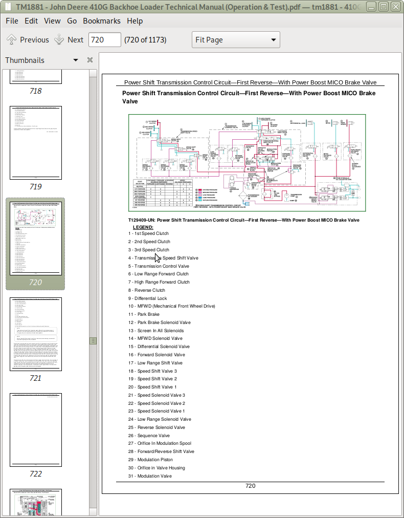
Power Shift Transmission Control Circuit342200224First Reverse342200224With Power Boost MICO Brake Valve
Power Shift Transmission Control Circuit342200224High Range (Fourth) Forward342200224With Power Boost MICO Brake Valve
Power Shift Transmission Control Circuit342200224Neutral With Park Brake Off342200224With Power Boost MICO Brake Valve
Power Shift Transmission Control Valve and Shift Valve342200224First Forward
Power Shift Transmission Control Valve and Shift Valve342200224First Reverse
Power Shift Transmission Control Valve and Shift Valve342200224High Range (Fourth) Forward
Power Shift Transmission Control Valve and Shift Valve Operation342200224Neutral
Power Shift Transmission Gear Flow
Service Brake Operation
Torque Converter Operation
Transmission Filter Operation
Transmission Pump Operation
15 - Diagnostic Information
Diagnose MFWD Malfunction
Diagnose Power Shift Power Train Malfunction
Diagnose Rear Axle Malfunction
Hydraulic Circuit Symbols
20 - Adjustments
Brake Bleeding Procedure
Brake Pedal Adjustment
Park Brake Release for Towing
Steering Angle Check and Adjust
Toe-In Check and Adjust
Tracking Angle Check and Adjust
25 - Tests
Brake Valve Leakage Test
Converter-In Relief Valve Test
Cooler In and Cooler Out Pressure Test
Differential Lock Pressure Test
JT05800 Digital Thermometer Installation
JT05801 Clamp-On Electronic Tachometer Installation
MFWD Pressure Test342200224If Equipped
Modulation Valve Pressure Test
Park Brake Release Pressure Test
Power Shift Low Range Forward, High Range Forward, Reverse and Speed Clutch Pressure Test
Power Shift Transmission Overall Test Connections, Ports, and Locations
Pump Flow Test
Reducing Valve Pressure Test
Solenoid Circuit Leakage Test
System Pressure Test
Torque Converter Stall Speed Test (S.N.342200224951254)
Torque Converter Stall Speed Test (S.N. 951255342200224 )
Transmission Oil Warm-Up Procedure
9025 - Hydraulic System
05 - Theory of Operation
Attachment Coupler Hydraulic Theory of Operation
Backhoe Auxiliary Flow Control Circuit Relief Valve
Backhoe Auxiliary Section
Backhoe Auxiliary Selective Flow Valve342200224Solenoid Energized (S.N. 342200224951254)
Backhoe Auxiliary Selective Flow Valve342200224Solenoid Energized (S.N. 951255342200224 )
Backhoe Boom Section342200224Boom Raise Position (Pilot Control) (S.N. 913484342200224 )
Backhoe Boom Section342200224Boom Raise Position (S.N. 342200224913483)
Backhoe Bucket Section342200224Bucket Curl Position (S.N. 342200224913483)
Backhoe Crowd Section342200224Crowd In Position (S.N. 342200224913483)
Backhoe Inlet Section with Swing Section Activated
Backhoe Swing Section342200224Swing Right Position
Backhoe Valve End Cap
Circuit Relief Valve with Anti-Cavitation342200224Loader and Backhoe_{33}
Circuit Relief Valve with Anti-Cavitation342200224Loader and Backhoe
Circuit Relief Valve without Anti-Cavitation and Load Sense Relief342200224Loader and Backhoe (S.N. 913480342200224 )
Circuit Relief Valve without Anti-Cavitation and Load Sense Relief Valve342200224Loader and Backhoe (S.N. 342200224913479)
Hydraulic Filter342200224Normal Operation
Hydraulic Filter Operation342200224Restricted
Hydraulic Pump Controls342200224Flow Limited (High Pressure) (S.N. 342200224951254)
Hydraulic Pump Controls342200224Full Flow (S.N. 342200224951254)
Hydraulic Pump Controls342200224Function Metering (S.N. 342200224907932)
Hydraulic Pump Controls342200224Function Metering (S.N. 907933342200224951254)
Hydraulic Pump Controls342200224Neutral (S.N. 342200224907932)
Hydraulic Pump Controls342200224Neutral (S.N. 907933342200224951254)
Hydraulic Pump342200224Full Stroke (S.N. 342200224951254)
Hydraulic Pump342200224Neutral Operation (S.N. 342200224951254)
Hydraulic Pump Operation (S.N. 951255342200224 )
Loader and Stabilizer Valve (S.N. 913480342200224 )
Loader Auxiliary Section342200224Load Position (S.N. 342200224913479)
Loader Boom Section342200224Boom Raise Position (S.N. 342200224913479)
Loader Bucket Section342200224Bucket Rollback Position (S.N. 342200224913479)
Loader Inlet Section with Bucket Section Activated (S.N. 342200224913479)
Loader Valve Load Sense Relief (S.N. 913480342200224 )
Loader Valve Outlet Section (S.N. 342200224913479)
Loader Valve Steering Load Sense Isolator (S.N. 913480342200224 )
Load Sense Isolator
Load Sense With All Functions in Neutral
Load Sense With Multiple Functions Activated (One Function Stalled)
Load Sense With Multiple Functions Activated
Load Sense With One Function Activated
Pattern Select Valve Operation (S.N. 913484342200224 )
Pilot Control Manifold Valve Operation (S.N. 913484342200224 )
Pilot Control Valve Theory of Operation (S.N. 913484342200224 )
Power Limiting Valve Operation (S.N. 951255342200224 )
Ride Control Hydraulic Circuit Component Location and Valve Operation342200224On Position (S.N. 342200224911132)
Ride Control Hydraulic Circuit Component Location and Valve Operation (S.N. 911133342200224911330)
Ride Control Hydraulic Circuit Component Location and Valve Operation (S.N. 911331342200224 )
Ride Control Hydraulic Component Location Circuit342200224Off (S.N. 342200224911132)
Secondary Steering
Steering342200224No Steering
Steering
15 - Diagnostic Information
Backhoe Hydraulic System (S.N. 342200224951254)
Backhoe Hydraulic System (S.N. 951255342200224 )
Diagnose Hydraulic System Problems
Diagnose Steering System Malfunctions
Hydraulic Component Location
Hydraulic System Schematic
20 - Adjustments
Adjusting Loader Bucket Self-Leveling Linkage and Return-to-Dig Switch (S.N. 342200224913479)
Backhoe Valve Linkage Adjustment342200224Four Lever If Equipped
Backhoe Valve Linkage Adjustment
Loader Bucket Self-Leveling Linkage and Return-to-Dig Switch Adjustment (S.N. 913480342200224 )
Loader Lever and Stabilizer Lever Adjustment (S.N. 913480342200224 )
Pilot Control Manifold Valve Accumulator Discharge Procedure
Pilot Control Pressure Adjustment (S.N. 913484342200224 )
Power Limiting Valve Calibration
Ride Control Accumulator Charge Check Procedure
Ride Control Accumulator Hydraulic Pressure Release Procedure
Selective Flow Valve Adjustment (S.N. 342200224951254)
Selective Flow Valve Adjustment (S.N. 951255342200224 )
25 - Tests
Charging the Ride Control Accumulator
Circuit Relief Valve Test With Remote Pump
Cylinder Leakage Test
Diagnostics Flow Charts
Flow Limiter Test (S.N. 342200224951254)
Function Drift Test
Hydraulic Circuit Pressure Release
Hydraulic Cylinder Drift Test Procedure
Hydraulic Oil Cooler Restriction Test
Hydraulic Oil Warm-Up Procedure
Hydraulic Return Pressure Test
JT02156A Digital Pressure And Temperature Analyzer Installation
JT05800 Digital Thermometer Installation_{54}
JT05801 Clamp-On Electronic Tachometer Installation_{39}
Load Sense Pressure Test (S.N. 342200224951254)
Load Sense Pressure Test (S.N. 951255342200224 )
Low Hydraulic Power
Pilot Control Pressure Test (S.N. 913484342200224 )
Power Limiting Valve Test (S.N. 951255342200224 )
Pre-Test Diagnostics
Pump Flow Test
Pump Load Sense Differential Pressure Test ( S.N. 342200224951254)
Pump Load Sense Differential Pressure Test (S.N. 951255342200224 )
Ride Control Accumulator342200224Discharge Procedure
Stabilizer Valve Lockout Leakage Test
Steering Cylinder Leakage Test
Steering System Leakage Test
9031 - Heating and Air Conditioning
A _ C Binary Pressure Switch Test (S.N. 926436342200224)
Air Conditioning Cab Harness (W10) Wiring Diagram
Air Conditioning Circuit342200224Operational Information
Air Conditioning Circuit342200224Schematic
Air Conditioning Circuit342200224Specifications
Air Conditioning Circuit Theory Of Operation
Air Conditioning Component Location (S.N. 342200224926435)
Air Conditioning Component Location (S.N. 926436342200224 )
Air Conditioning Compressor Harness (W9) Wiring Diagram
Air Conditioning Switch342200224Test
Air Conditioning System342200224Test Leak
Blower Resistor342200224Test
Blower Switch342200224Test
Compressor Clutch Coil342200224Test
Diagnose Air Conditioning Electrical Malfunctions
Diagnostic Chart Pressure
Expansion Valve342200224Test Operation
Expansion Valve 342200224Theory Of Operation
Freeze Control Switch342200224Test
Freeze Control342200224Test
Heater Blower Circuit342200224Operational Information
Heater Blower Circuit342200224Schematic
Heater Blower Circuit Theory Of Operation
Heater Blower Motor342200224Test
High Pressure Switch342200224Check (S.N. 342200224926435)
High Pressure Switch342200224Test (S.N. 342200224926435)
Low Pressure Switch342200224Check (S.N. 342200224926435)
Low Pressure Switch342200224Test (S.N. 342200224926435)
Other Materials
Proper Refrigerant Handling_{27}
Proper Refrigerant Handling_{32}
Proper Refrigerant Handling
R12 And R134a Refrigerant Cautions
R134a Air Conditioning System Test
R134a Compressor Oil342200224Charge Check
R134a Compressor Oil342200224Charge
R134a Compressor Oil342200224Removal
R134a Refrigerant342200224Cautions_{40}
R134a Refrigerant342200224Cautions
R134a Refrigerant Recover, Recycle and Charge Station Installation Procedure
R134a Refrigerant342200224Theory Of Operation
R134a System342200224Charge
R134a System Cleaning Procedure
R134a System342200224Evacuate
R134a System342200224Flush
R134a System342200224Purge
Receiver _ Dryer342200224Theory Of Operation
Refrigerant Hoses And Tubing342200224Inspection
Relief Valve Compressor342200224Theory Of Operation
Service Equipment and Tools
Service Equipment and Tools
Special or Essential Tools_{07}
Special or Essential Tools
Specifications
Specifications
Switch Freeze Control342200224Theory Of Operation
Temperature Control342200224Theory Of Operation
John Deere 410G Backhoe Loader Technical Manual (Operation & Test) (TM1881)
![]()